Pocuter One
Be aware, I'm going to continue writing and improving on this article. Maybe the parts I release are already useful for someone.
The Pocuter One is a project I've backed on Kickstarter a while ago. I received their package right before Easter holidays in Germany, so I had some time to assemble it.
While I was pretty shocked to learn that I had to solder a battery onto this mini computer for it to work, I'm pretty happy with the result. Since I'm pretty much new to working with hardware, I want to share what I had to do in order to get to a result.
If you haven't checked out the documentation of the Pocuter One, it's definitely something to look at first.
WatchKit assembly
There are a few things that need to be done before playing around with apps:
- Solder a battery to the chip
- Assemble the watch itself
Soldering the battery
The very first one was the most intimidating for me as someone who doesn't have much experience
with hardware. I wasn't sure which cable needs to go to which pole, since the only thing I saw
was a red and a black cable and the + and - symbols on the chip. So my first
research was about whether the red or the black cable is + or -.
When I researched cable color codes, I found conflicting information based on what part of the world you are in. I know that the company that sells the computer is based in Germany, but as far as I understand it, the parts come from China.
Long story short, in the Pocuter Discord, people shared pictures of how they put batteries on the board. I could infer that the red
cable goes to the + pole and the black cable to the - pole. I can definitly
recommend joining their Discord as they seem to be very active and helpful regarding support.
To be able to solder a cable, I had to cut the outer parts of the wire, so the metallic inside is visible. There are specialized tools for doing that and trying to cut it off with something sharp resulted in losing quite a bit of the wire itself. I then found a small tool I could use that I got from some random hackathon or conference that I attended. It worked out, but it was quite painful to get it done. Anyways, once you see the metallic inside of the red and the black wires from the battery, you can solder it. I opened it a couple of millimeters, so I was sure I can hit it with my relatively big soldering iron.
I put the cables from "below" into the holes. "Below" means when folding the screen on top of the chip as it needs to be put in the watch case, the battery is below the chip. The red and black cables from the battery then don't need to be wrapped around the chip in the small watch case.
I then started soldering with the black one on the - pole. I thought it's probably easier
to put the soldering down on the less exposed port first, so fixing something wouldn't automatically
mean I have to remove the potentially working and more exposed + port as well.
While soldering, the watch started to boot up. For me, this was the sign that the soldering worked out well and I made sure both cables were properly fixed. I made sure the soldered metal wasn't too high, so the screen wouldn't be hurt by that. I had to take off some of the soldering again by using the hot soldering iron and gently draw something away from it again. I guess it was pure luck that I didn't destroy anything while doing that - the pocuter continued to work!
If the watch turned off at some point during the assembly, it wasn't because of my lack of experience with the soldering: The included battery runs out pretty quickly. I think when using the "Clock" application, it's running for about 1.5 hours after having the USB connected for an extended period of time.
Assembly of the watch kit
Ok, so this looked pretty straightforward. The screen only has one place where it can go. I could see from the outside where the USB port and the buttons / knobs should be. The buttons were a bit too hard to put in and it felt a bit wrong to push them so hard into it. I made it, but once I put in all the screws, I couldn't really push the buttons at all or they were "always pushed". This felt really wrong.
After checking the Discord again, I saw that people used a file to make the inside of the button a bit wider, so I tried that out myself: Unscrew the watch case, take out the knobs again. Equipped with a small file for fingernails, I could scrub a little bit away from the sides from the inside of the "U"-shaped buttons. When I put the buttons into the watch again, they were fitting way better than before and I didn't even have to push them into the case - they actually fit really nice after using the file. The problems with "always pushed" buttons or having a hard time to press anything at all, vanished completely.
Setting up the wrist band worked well for me: I had to put the metal bars into one hole, then press and hold the tiny metal piece so the whole bar fits into the side of the watch and once it inside the sides, find the other hole by wiggling it around a bit. It took me a few tries but it worked out eventually and didn't take too long.
Applications
There are a couple of apps you can download and add to the pocuter. This is actually quite easy
to do, but the documentation was a bit lacking. The SD card from the pocuter should be plugged
into a regular computer. The apps that can currently be downloaded are .zip files. In
these, there is a folder named with a number and in that folder, there is a file called esp32c3.app. On the SD card, these need to be put into an apps folder, keeping
the numbered folder.
To make it clear, the structure of the SD card should look like this:
1 | |
2 | |
3 | |
4 | |
5 | |
6 | |
7 | |
8 | |
9 | |
10 | |
11 | |
12 | |
13 | |
14 | |
15 | |
16 | |
17 | |
18 | |
Once the apps are put onto the SD card in the proper structure, putting it back into the pocuter and restarting it yielded all the apps in there.
Writing my own app took a bit longer...
Writing an app for the Pocuter
To develop an application for the Pocuter, it's necessary to have a build setup that allows to compile code to the Arduino. It's possible to do this in different ways, the easiest is to use the Arduino IDE. In the current pocuter documentation, it's documented how to setup the Arduino IDE 1.x, but there is a version 2 already. I've made it work with version 2 on my Mac before I got a working build setup with my currently favorite IDE, VSCode. I'm documenting how I set it up in both ways.
Setup Arduino IDE 2.x
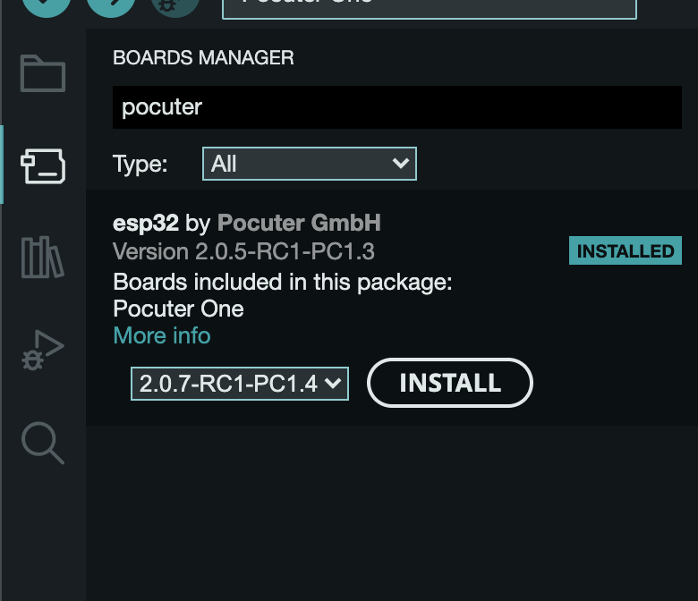
First thing I had to do is adding the additional boards manager URL. They provided the URL https://raw.githubusercontent.com/pocuter/ArduinoBoard/main/pocuter_arduino.json in their documentation and this value can be put into Arduino IDE -> Settings ... > "Additional Boards Manager URLs". After doing
this, the Pocuter board should be included in the "boards manager". The boards manager is the
second item on the left side.
As far as I understood it, you need the various boards to be able to actually compile code for them. As soon as the board is there, writing an application and compiling it should work.
Connecting the Pocuter
This one was tricky when working with my Mac OS Ventura. There are quite a few blog posts out
there mentioning to install some third party USB drivers. Most of them seem to be outdated
though and when I tried out a couple of these, the USB connection still didn't work for me. I
took me a while to understand one crucial thing: USB cables are not equal to USB cables. There
are some cables that only deliver current but no data. If you happen to try and use one of the
"current-only" cables, you won't be able to find your Pocuter through the serial ports at all.
If you don't see any changes in ls /dev/cu.* when plugging the cable in or removing it,
the cable itself may be the culprit.
Uploading code to the pocuter
Ok, so I've seen multiple ways to do this, each of them have their own pros and cons:
- Update the SD card and write into the
/apps/folder - Upload compiled code directly through the USB serial port
- Upload through HTTP through an app installed on the pocuter
1. Using SD card
The SD card approach is the one mentioned in the documentation and is done through multiple steps:
- Compile the new version of your app (several steps)
- Remove the SD card from the pocuter
- Put the SD card into a reader
- Mount it on the computer
- Copy the compiled version into the
/apps/folder on the SD card - Unmount the SD card from the computer
- Put the SD card back into the pocuter
- Restart the pocuter
While these steps worked really well for me, especially when I had the issue with the USB cable, this is quite a tedious process and involves a lot of manual work that can't easily be automated. It works for releases, but testing intermediate versions of your app takes quite some time.
2. Using USB
The second option is to upload compiled code directly to the pocuter. When trying to upload code
through the Arduino IDE 2.x, I faced another issue. The error told me something like Property 'upload.tool' is undefined or Property 'upload.tool.serial' is undefined. It looks like Arduino IDE 2.x
changed a bit regarding the boards.txt files, which seem to be the instructions for how
to upload code to the board.
First of all, the I had to install the version 2.0.5-RC1-PC1.3 of the Pocuter library
because the newer version didn't compile for me. After using that version and seeing the error above,
I had to change the file $HOME/Library/Arduino15/packages/esp32/hardware/esp32/2.0.5-RC1-PC1.3/boards.txt to make
this work. There is a line pocuterone.upload.tool=esptool_py which needed to be changed
to pocuterone.upload.tool.serial=esptool_py. After this change, uploading through the
Arduino IDE 2.x worked.
Since this worked now, I could even change my setup to make uploading work through the command
line. This improves my development experience, because I can use my favorite IDE instead of the
Arduino IDE to prepare the Sketches (VSCode) and then use the command line tool arduino-cli to compile and upload it. My current setup consists of two steps to make the compilation and upload
work:
arduino-cli compile -b "$FQBN" -p "$USB_PORT" --build-path "$BUILD_PATH"arduino-cli upload --input-dir "$BUILD_PATH" -b "$FQBN" -p "$USB_PORT"
The FQBN I got from checking the boards list (arduino-cli board listall), which gave me esp32:esp32:pocuterone identifier. The USB_PORT I get
by using find /dev/cu.usb* when the Pocuter is connected with a USB cable that supports
data transfer - as I mentioned earlier, this took me a while to figure out. The BUILD_PATH is set to ./build so it doesn't use some temporary directory and always needs to recompile
if something fails during upload.
The bad side of this is that uploading code through USB is only replacing the current version. It will not persist as an app and you still need to write to the SD card in a later step.
Using HTTP server
I have to admit, I haven't tried this yet, but someone in the Pocuter Discord shared their deployment tool. From my understanding, you can install this Code Upload Server app to directly write on the SD card. That means you'll be able to quickly write the whole app on it instead of using the SD card approach mentioned earlier.